The most costly decision in product development is committing to production before a design has been properly validated. When tooling costs, lead times, and revision overhead are considered together, design flaws discovered after production begins represent a significant financial exposure. The way to manage that risk is physical validation before manufacturing begins. That process is called prototyping.
What is a prototype?
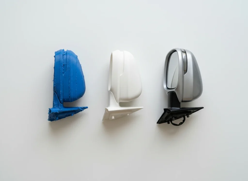
A prototype is an early-stage physical model produced to validate the design of a product or component. It is not manufactured using production tooling; instead, separate production methods are used so that design changes can be incorporated quickly and at low cost.
The core function of a prototype is to test the assumptions embedded in a design file against real-world conditions. Do the dimensions hold? Do the parts fit together correctly? How does the material behave under load? How does this form feel in the user’s hand? These questions are not answered on a CAD screen they are answered on the physical part.
What is rapid prototyping, and how does it differ from traditional methods?
Traditional prototyping relied on CNC machining, casting tooling, and extended supply chains. Obtaining a single prototype could take weeks or months. Every design revision restarted the process.
Rapid prototyping describes the technologies and processes that reduce the time from digital design file to physical part to a matter of days or hours. 3D printing is the core technology in this field; vacuum casting, reaction injection molding (RIM), and hybrid approaches also fall within this category.
To put the difference in concrete terms: obtaining a plastic enclosure prototype through traditional methods required 4-6 weeks and a substantial budget. The same part can now be delivered via industrial 3D printing within 24-72 hours.
Types of prototypes
Not all prototypes serve the same purpose. The type of prototype required is determined by where you are in the product development process and what specific question the prototype needs to answer.
Visual and concept prototypes
Visual prototypes are produced to evaluate the form, proportions, and overall aesthetics of a product. Mechanical strength and material properties are secondary at this stage; the priority is understanding whether the part is correctly structured visually and ergonomically. Customer presentations, internal approval processes, and user testing are the primary applications.
SLA/DLP resin printing is a commonly chosen method for this purpose. Surface quality is high, dimensional accuracy is good, and the parts are well-suited for painting and post-processing.
Functional test prototypes
Functional test prototypes are produced to be tested under real load, heat, vibration, or usage conditions. The mechanical properties of these parts must be close to those of the final product, which makes material selection a determining factor.
HP MJF and SLS technologies produce isotropic mechanical properties meaning similar performance in all axes regardless of print orientation. This characteristic matters in functional testing for parts exposed to directional loads. Carbon fiber reinforced filaments and high-temperature resins are also commonly used materials in this category.
Methods used in rapid prototyping
FDM (Fused Deposition Modeling)
FDM printing melts thermoplastic filament and builds parts layer by layer. It is suitable for large-volume parts, durable functional prototypes, and mechanical test components. It works with a wide range of materials including PLA, ABS, PETG, PA, PC, and carbon fiber reinforced filaments. For a full technical breakdown, see our FDM 3D printing guide.
Industrial FDM machines differ from desktop printers in dimensional consistency, thermal management, and the ability to process high-performance engineering thermoplastics. Materials that require a heated, enclosed chamber can only be reliably processed on industrial-grade equipment.
SLA / DLP (Resin printing)
SLA and DLP technologies cure photopolymer resin using UV light. Surface quality and dimensional accuracy are superior to FDM. Visual prototypes, thin-walled parts, medical models, and master patterns for vacuum casting are the primary applications. For a detailed comparison of both technologies, see our SLA and DLP printing guide.
Resin selection is made based on the intended use of the part: standard prototyping resins, high-temperature formulations, flexible variants, and biocompatible dental resins address different requirements. Technical comparisons are available on our material comparison page.
SLS (Selective Laser Sintering)
SLS printing sinters polymer powder layers using a laser. It requires no support structures, which means complex geometries, internal channels, and interlocking mechanisms can be produced in a single build. PA12 is the most widely used material in this process, offering solid mechanical properties, low moisture absorption, and chemical resistance.
HP MJF (Multi Jet Fusion)
HP MJF technology offers higher throughput and a more homogeneous microstructure compared to SLS. Isotropic mechanical properties, good surface quality, and repeatable dimensional results make this technology well-suited for bridge tooling scenarios. For batch sizes between 10 and several hundred parts, per-unit cost falls between SLS and injection molding.
Vacuum silicone casting
Vacuum casting involves producing an RTV silicone mold from a master part, then casting 10–50 polyurethane parts from that mold. In terms of surface quality and mechanical properties, it is the rapid prototyping method that comes closest to injection-molded output. For a full process breakdown, see our vacuum casting guide.
The use case is well-defined: when ABS- or PP-like mechanical properties are needed at a fraction of injection mold cost. Small-batch functional testing, customer pilots, and market validation runs are the typical scenarios.
Why does material selection matter?
One of the more common errors in prototyping is selecting a material without regard to the final product’s requirements. If only form and aesthetics are being evaluated, this can be acceptable. But when mechanical testing, assembly validation, or thermal analysis is involved, material selection directly determines the test result.
An automotive interior component requiring heat resistance above 85°C cannot be meaningfully tested in standard PLA. A medical device component must be tested with a biocompatible material. A flexible seal or fitting requires a TPU or silicone-based material evaluated against the specific application scenario.
For guidance on material and method selection, our DFM analysis service provides recommendations based on part geometry, tolerance requirements, and operating conditions.
How does the prototyping cycle work?
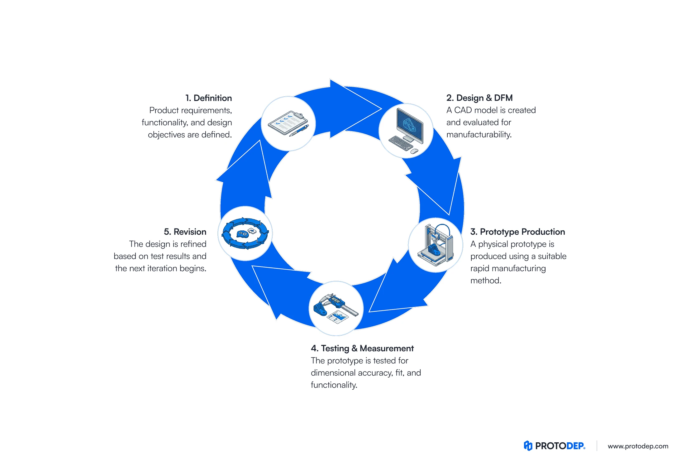
Prototyping is not a single step. Most product development programs involve multiple cycles; each one answers the questions raised by the previous stage and may open new validation requirements. Understanding this structure from the outset allows for realistic budget and schedule planning.
1. Define
Each cycle begins by clearly identifying what questions need to be answered. “What is this prototype for?” drives every subsequent technical decision. If only form evaluation is needed, specifying functional test materials wastes time and budget. If thermal loading is being tested, investing in surface finish quality is not the priority.
2. Design review and DFM check
The CAD file is reviewed and adapted for the chosen production method. Wall thicknesses, draft angles, support geometries, and tolerances are examined at this stage. DFM analysis identifies geometric issues that would cause production failures before they reach the build stage, which shortens the overall revision cycle.
3. Production
The part is produced using the selected method and material. Lead times vary by technology: a large enclosure via FDM can be delivered in 24 hours; a precision optical component via SLA in 1-2 days; a 10-20 piece PU casting run via vacuum casting in 5-7 days.
4. Testing and evaluation
The part is tested against the criteria defined in the first step. Dimensional inspection, assembly fit checks, load testing, or user evaluation take place here. Findings are documented and fed back into the design.
5. Revision and next cycle
Minor revisions are retested in a limited scope in the next cycle; major design changes initiate a full new cycle. In practice, most products go through 2 to 4 cycles. This number varies with part complexity, sector regulatory requirements, and the maturity of the initial design.
The number of cycles is difficult to predict in advance, but the cost per cycle can be kept low. Rapid prototyping technologies reduce the unit cost of each revision, enabling engineering teams to physically test more design hypotheses and arrive at production tooling with a more mature, validated design.
From prototype to production: bridge tooling
The most consequential decision in product development is when to commit to injection tooling. An aluminum or steel mold is a significant capital investment; once the design is locked, revision options are both expensive and time-consuming.
Entering tooling before the design is fully mature turns this risk into a real cost. An out-of-tolerance channel, a misplaced boss, or a revised reference surface each translate into tooling modification or re-tooling expense.
Bridge tooling addresses this gap. Rapid prototyping methods validate the design; low-volume production fills demand while volume grows. The decision to invest in hard tooling is made from a validated design baseline.
Which industries use rapid prototyping?
Any industry that develops physical products benefits from this process. Application intensity is particularly high in certain sectors.
Automotive and mobility: Interior components, ducting and connector parts, aerodynamic test models, and EV battery enclosures are among the most active application areas. See our automotive sector page for more detail.
Medical and healthcare technologies: Surgical guides, patient-specific anatomical models, and device enclosures are prominent applications. Certification processes make prototyping a required step. More information is available on our medical sector page.
Defense and aerospace: Lightweight components, thermal test parts, and geometric validation models represent the bulk of prototyping requirements in this sector. Visit our defense and security page for details.
Industrial machinery and robotics: Custom fixtures, assembly jigs, cable guides, and adapters are typically needed in small quantities and short lead times. Our industrial machinery page covers these applications.
What to clarify before placing a prototype order
Purpose of the part: Visual evaluation or functional test? This distinction determines both technology and material selection.
Tolerance requirements: Standard 3D printing tolerances are sufficient for most prototyping applications. For sealing surfaces, press-fit connections, or parts requiring precise measurement, tolerance planning directly affects the choice of production method.
Surface quality: If the prototype will be used as a master pattern for casting, surface roughness becomes a critical parameter. SLA printing or a post-processing CNC step should be considered in these cases.
Quantity and lead time: For production scenarios ranging from a single part to 50 pieces, the balance of cost, speed, and quality brings different methods to the front. We recommend working through this decision with our engineering support team.
Frequently asked questions
3D printing is a widely used method in rapid prototyping, but prototyping is not limited to it. Vacuum casting, RIM, CNC, and hybrid processes all fall within this category. The appropriate method is determined by the requirements of the specific part.
Most likely not and in most cases, that is fine. The purpose of prototyping is not to fully simulate the final product; it is to answer specific design questions. When functional testing requires material properties to be close to production-grade, that requirement is factored into method and material selection.
This threshold varies with part complexity, size, and material. As a general reference: for simple geometries, injection molding tends to become economical above 500-1,000 parts. For complex parts, this threshold may be lower.
Next steps
Design flaws caught before tooling cost a fraction of what they cost afterward. In that sense, prototyping is not a cost item on the path to production it is a risk management tool that pays for itself when a single late-stage revision is avoided.
You can review our prototyping services or upload your files directly through our instant quote form. If you are unsure which method is right for your project, our engineering team is available to review your files and advise.
Quote in Seconds, Parts in Days
Upload your 3D CAD files, select your manufacturing technology, and receive an instant cost analysis. Zero wait time, no minimum order requirements.